Single Screen Navigation
Click on images for larger view
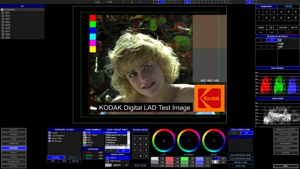
The XENA software was designed for efficient project navigation, with a universal interface that displays the following at all times:
-
Current Image – The contents of the scan buffer, processed by the currently selected Scan and Exposure setups (see below).
-
Project Tree – Displays the contents of your project, organized by user-defined folders. All programmed scan session documents are viewable. A context sensitive mouse-driven menu will create, rename and delete folders and session documents.
-
Transport Controls – You can navigate and define the film positon, as well as put XENA into load/unload mode.
-
Screen Selection Buttons – These buttons change the context screens on the lower third and right side of the screen.
-
Top Toolbar (See below)
The lower third and right side of the screen are context sensitive and change with the button selections, even during scan time. Any feature you need is only one mouse click away. The Top Toolbar allows you acces to:
-
Channel View – View individual color channels, alpha channel or dirt mattes independently.
-
Pixel Sample – You can measure screen pixels with the mouse for their RGB values displayed as 12 bit, 10 bit, 8 bit or floating point values.
-
Safe Display – You can toggle safe title/action display on and off.
The software runs on a single 1920 x 1080 resolution monitor. Full screen image viewing can be toggled on and off, or a second monitor can display simultaneous full screen images and/or waveform display. An optional SDI output card allows you to send 2K, HD or SD images to a calibrated projector or client monitor.
The geometry screen allows you to quickly and easily create and store scan setups. You can scan any user-defined resolution, up to the maximum resolution of the camera currently installed. You can scan any region of the camera sensor, with X and Y offsets from center. Scan setups are stored either globally or in your specific project folder. Key features include:
- Format – Selects your film gauge and perf setting.
- Image Type – Selects positive or negative film.
- Capture Resolution – This is actual image dimension scanned by the camera. For example, suppose you have a 16MP camera mounted, which has a sensor resolution of 4872 x 3248. You select a standard 4K capture resolution of 4096 x 3112, which is a subset of the full resolution of the camera.
- Capture Offset – If your capture resolution is lower than the camera’s maximum resolution, you can designate an X-Y offset from center of the sensor here. This feature is useful in performing critical aspect ratio lineup to setup films (like SMPTE RP40) or to framing tests supplied by a cinematographer.
- File Resolution – This is the final dimension in pixels of the scan image that will be saved to disk. Suppose your doing “Super 2K” scanning. You might set the capture resolution to 4096 x 3112, and set the file output to 2048 x 1556. There is no restriction to combinations between capture and file resolutions, only those imposed by the specific hardware you use.
- Geometry – The scan capture may then be optionally scaled with any combination of user-defined X and Y sizing, X and Y translation, or rotation. All scaling is performed in real time within the NVidia workstation graphics card using advanced filtering techniques, yielding maximum image sharpness. In the case of the “Super 2K” example, you would need to scale the image down from 4K to 2K. However, you are unlimited in how you may apply scaling. Post-capture scaling capability is very useful in many situations, like unsqueezing of anamorphic images, or for quick dailies setups. You can also flop the image for proper image orientation between negative and positive film, and you can flip the image to compensate for A or B wind threading. All of these settings may be applied to live scans or imported reference files with instant visual feedback, making geometry calibration fast and painless.
- Calibration Status– Verifies the presence and creation dates of your sensor correction and optional digital stablization calibrations.
- Keypad Entry – XENA software is designed for optional use with a tablet or mouse-only operation, so you will always have a software keypad available with only the valid characters for the specific operation. Rapid data entry with a keyboard is also supported.
- Capture Diagram – The geometry window displays a color-coded graphic representation of the scanned image before and after scaling, referenced to the full resolution of the sensor. This helps you verify that the scan setup design achieves what you want it to do.
Exposure & Color Correction
The exposure screen is a powerful inteface to set up all aspects of exposure and color correction, that are saved into a single file called an Exposure Setup. The following settings are included:
-
Scan Channels – You can select between RBG for color scanning, RGB + Matte to include an infrared dirt map, Black & White, or you can scan just one color channel at a time, which is useful for scanning archival color separation masters or 3-strip Technicolor original negatives.
-
Exposure – Here you set the LED exposure time for each channel. Scan times are set and accurate to one microsecond (one millionth of a second). When scanning with color cameras, a single exposure time is set, but the intensity of each LED color channel can be set for easy color balancing of scans.
-
User Lookup Table – As part XENA’s open architecture, you can load a 3D or 2D user-defined lookup table. The text-based file format is provided to you. This allows you to use third party tools or your own in-house calibration system for creating custom scanning LUTs.
-
Color Space – Selects between linear scanning for positive film, or Kodak Cineon code value for negative film.
-
Invert – Enabled for negative film.
-
Keypad Entry – As found in the geometry screen, you may use this object for data entry as an alternative to the keyboard.
-
Color Correction – Standard vector, primary and limited secondary (saturation and contrast) color correction tools are available for post-capture processing prior to image display and saving to disk. Excessive use of these tools is not recommended for scanning of negative materials for digital intermediate feature work, but are invaluable for setting global correction of master positive and print materials, allowing you to set the color in close range for the scene-to-scene color correction stage. These tools are especially useful for achieving contrast balance in print materials to prevent clipping and loss of shadow material.
-
Field Correction – Enables linearity, dark current and light field correction of selected scan channels (recommended at all times).
-
Dirt Matte – If the infrared dirt matte hardware and software options are installed, the matte is calibrated and enabled here. Dirt mattes can be embedded in the DPX file without additional file size, or as a alpha channel in standard image file formats, like SGI and TIFF.
Scanning session documents can be either created with the XENA software, or with a separate Windows application that’s included on another workstation. When loaded into your application folder, you can perform easy, point and click batch scanning. Embedded in the scanning screen is the ability to edit scanning event parameters on the fly. This is helpful if you find a lineup error, or encounter a clip or take that has inconsistent exposure. You can over-ride exposure in any scan event and save it back to the scan session document.
This screen enables you to customize the viewing of your scans without affecting the images saved to disk. Feature include:
- Aspect Ratio – Presets of the most common aspect ratios plus user-defined viewing ratios are set here. Custom presets can be stored globally in the application, or in specific project folders.
- Border – You can define a custom border color and turn it on and off.
- Masking – You can matte the image with black borders of any aspect ratio and set their opacity.
- Safe Area Display – Standard and user-defined safe action, safe title and image center targets can be enabled/disabled in any combination. You can define the color of each display. The Safe Display can be toggled on and off with the Top Toolbar, even when the guides window is inactive.
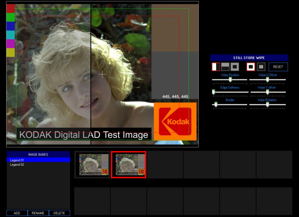
This is a powerful feature normally found only in high-end color correction programs, enabling you to capture and store scans and imported reference files into image banks within your project folder. You can then enable split screen wipes during color correction and live scanning for color matching or refernce.
Another high-end feature rare to film scanners. The dual scope window includes the following features:
-
Parade, Luminance, RGB Waveform and Vectorscope Display
-
Color or monochrome trace display
-
12 Bit, 10bit, 8 bit, Floating Point or Cineon Code Value Scale Selection
-
Log To Linear Viewing Capability
-
Scale and Trace Intensity Settings
Manual retouching of dirt and scratches can be achieved in the retouch screen. Pixels can be cloned from adjacent pixels, or copied from previoius or subsequent frames. Our advanced cloning interface allows to choose from split screens of different sizes, align the images with X offet, Y offset and zoom to enable seemless pixel cloning.
It is even possible to retouch while simultaneously scanning by selecting CPU-based processing instead of Graphics-card processing.
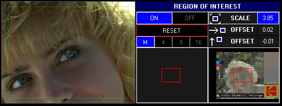
Region of Interest
The region-of-interest control panel allows you to make custom selections for detailed viewing. It does not affect the scan, and can be enabled and disabled at all times.


